

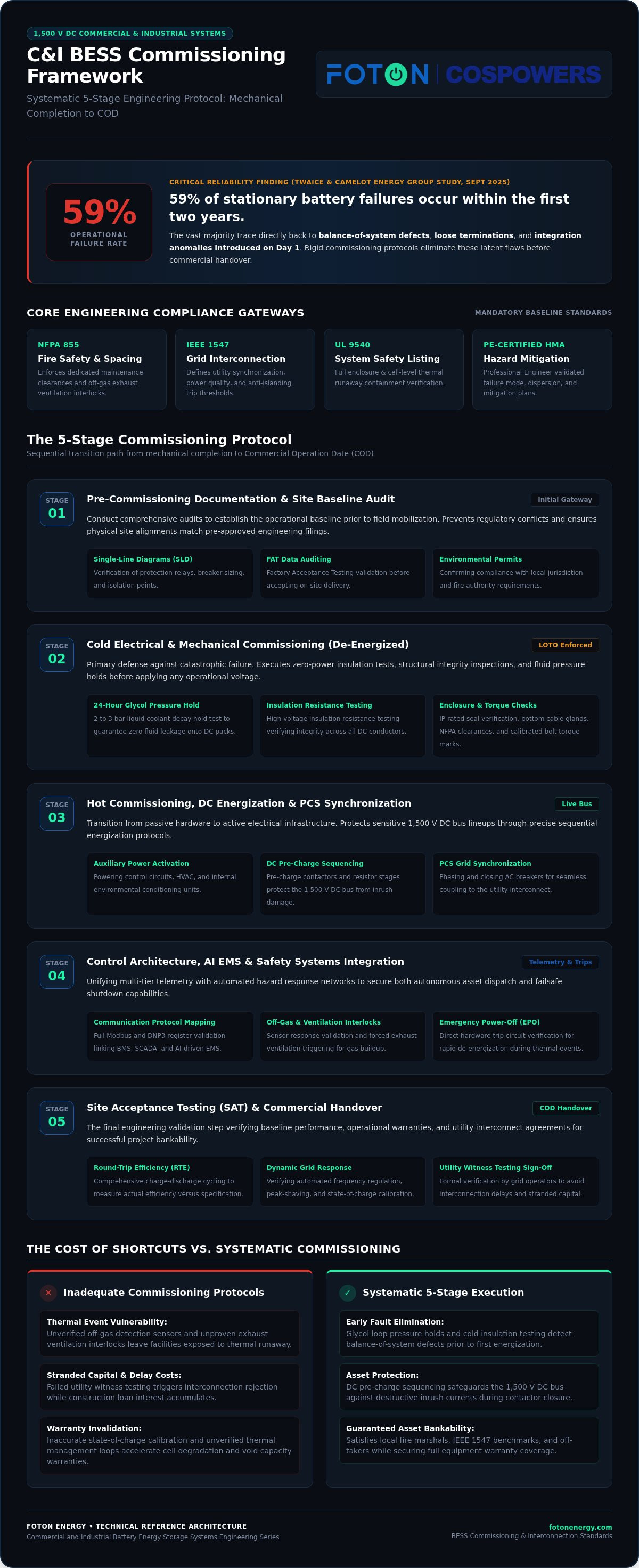
According to a September 2025 TWAICE and Camelot Energy Group reliability study, 59% of all stationary battery failures occur within the first two years of operation, with the vast majority tracing directly back to balance-of-system defects, loose terminations, and integration anomalies introduced on day one. If you feel the intense pressure of coordinating utility witness testing while managing the risks of high-density 1,500 V DC lineups, you aren't alone. Mastering exactly how to commission a C&I BESS with systematic engineering precision is the single most effective way to eliminate thermal risks, protect warranties, and avoid costly grid interconnection delays.
This comprehensive 2026 engineering guide delivers an authoritative, stage-by-stage sequence to transition your energy storage assets seamlessly from mechanical completion to commercial operation. You'll gain a battle-tested roadmap covering cold electrical insulation testing, DC pre-charge contactor sequencing, multi-tier BMS and EMS communication mapping, and full compliance with updated standards such as NFPA 855 and IEEE 1547. Below, we examine the critical gateways, safety interlocks, and site acceptance testing protocols required to guarantee long-term asset bankability.
Key Takeaways
- Master the four-phase engineering sequence that defines how to commission a C&I BESS safely, protecting equipment warranties and eliminating initial energization risks.
- Execute rigorous de-energized protocols, including glycol loop pressure holds and high-voltage insulation resistance testing, to catch balance-of-system faults early.
- Follow precise DC pre-charge resistor sequencing and inverter synchronization to protect sensitive 1,500 V DC bus architectures from destructive inrush currents.
- Integrate multi-tier BMS registers, AI-driven EMS platforms, and emergency trip interlocks to guarantee autonomous optimization and code-compliant fire safety.
- Validate round-trip efficiency and dynamic grid response through comprehensive site acceptance testing to secure rapid utility sign-off and stakeholder bankability.
What Is C&I BESS Commissioning and Why Is It Critical?
Commercial and industrial battery energy storage commissioning is the rigorous engineering gateway that validates whether physical equipment functions as an integrated, resilient system. It bridges the critical divide between mechanical completion and Commercial Operation Date (COD). Without this structured progression, stationary batteries remain unverified assets vulnerable to hidden wiring faults, control logic conflicts, and safety trip failures. Knowing how to commission a C&I BESS correctly transforms complex hardware into a bankable, revenue-generating facility that satisfies local fire marshals, electric utilities, and off-takers alike.
Rigorous commissioning begins well before touching field equipment. Under updated standards like NFPA 855, teams must conduct comprehensive document audits, including Professional Engineer-certified Hazard Mitigation Analyses (HMAs) and UL 9540 listing certifications. Aligning design documentation with grid-interconnection benchmarks like IEEE 1547 establishes the baseline necessary to avoid operational disputes later.
The True Cost of Inadequate Commissioning Protocols
Shortcuts during initial startup introduce latent defects that can jeopardize the entire project lifecycle. A failure to validate off-gas detection sensors or exhaust ventilation interlocks leaves facilities exposed to unmitigated thermal events. Beyond physical safety, missing witness-testing requirements directly triggers utility rejection, stranding capital while construction loan interest accrues. Inaccurate state-of-charge calibration and unverified thermal management loops also accelerate cell degradation, instantly voiding manufacturer capacity warranties.
Overview of the Five Critical Commissioning Stages
Executing a flawless site handover requires disciplined progression through five interconnected phases:
- Stage 1: Pre-Commissioning Documentation and Site Audit: Reviewing single-line diagrams, factory acceptance test (FAT) data, and environmental permits to establish a verified baseline.
- Stage 2: Cold Electrical and Mechanical Commissioning: Verifying high-voltage insulation resistance, bolt torque marks, and liquid coolant loop pressure decay under strict Lockout/Tagout (LOTO) safety controls.
- Stage 3: Hot Commissioning and Energization: Powering auxiliary control circuits, executing DC pre-charge resistor sequences, and synchronizing power conversion systems (PCS) with the local grid.
- Stage 4: Control Architecture and Safety Integration: Mapping Modbus or DNP3 communication registers between the battery management system (BMS), site SCADA, and intelligent energy management systems (EMS) while proving emergency power-off loops.
- Stage 5: Site Acceptance Testing (SAT) and Handover: Validating capacity, round-trip efficiency, and automated frequency or peak-shaving responses prior to formal utility sign-off.
Understanding how to commission a C&I BESS through these five gates guarantees that high-density storage hardware delivers the performance and safety stakeholders demand.
Phase 1: Pre-Commissioning Verification and Cold Electrical Testing
De-energized cold testing serves as your primary defense against catastrophic equipment failure. Before applying a single volt of operational power, field engineers must verify that physical assemblies, insulation barriers, and mechanical safety interfaces conform precisely to engineering submittals. Approaching how to commission a C&I BESS through systematic cold testing eliminates latent assembly flaws before they manifest as destructive short circuits.
Mechanical and Environmental Enclosure Audits
Field verification begins at the perimeter. Technicians must inspect external IP-rated enclosure seals, door gaskets, and bottom cable glands to prevent water ingress. Under updated NFPA 855 spatial guidelines, verify dedicated maintenance clearances around all modular enclosures. For modern liquid-cooled architectures, technicians must execute a 2 to 3 bar glycol loop pressure decay hold test over 24 hours. Confirming zero fluid loss across manifold junctions prevents internal coolant leaks onto live DC assemblies later.
De-Energized Electrical Integrity and Grounding Tests
Torque relaxation remains a leading cause of balance-of-system hot spots. Engineers must verify torque calibration marks across all DC busbar links and cell module terminals using calibrated click-type torque wrenches. Measure earth ground resistance across enclosure grounding pads to confirm a low-impedance pathway below 5 ohms.
Insulation resistance (IR) megohmmeter testing verifies dielectric boundaries across 1,500 V DC architectures:
- Apply 1,000 V DC or 2,500 V DC test voltages across isolated DC positive, negative, and chassis grounds.
- Ensure measured insulation resistance exceeds 100 megohms at reference ambient conditions, well above the 1 megohm per kilovolt baseline.
- Verify a Polarization Index (PI) of 2.0 or higher and a Dielectric Absorption Ratio (DAR) of at least 1.4.
- Confirm string open-circuit voltage polarity across all racks using digital multimeters before inserting high-voltage DC fuses.
Auxiliary Subsystems and E-Stop Loop Validation
Energize low-voltage AC auxiliary distribution panels independently to establish enclosure environmental control. Confirm uninterruptible power supply (UPS) operational autonomy to ensure critical control boards remain powered during an outage. Technicians must mechanically depress every hardwired Emergency Power Off (EPO) pushbutton to verify instantaneous, fail-safe tripping of shunt-trip breakers. Finally, validate that off-gas sensors and hydrogen purge ventilation interlocks activate at lower flammability limit thresholds below 25%. Partnering with seasoned specialists through turnkey engineering consulting ensures these complex cold checklists satisfy strict insurer criteria before hot energization begins.
Phase 2: Hot Commissioning, DC Energization, and Inverter Synchronization
Transitioning from de-energized inspections to hot commissioning demands uncompromising procedural discipline. Live voltage introduces immediate arc-flash and equipment damage hazards if current flows are uncontrolled. Understanding how to commission a C&I BESS during initial energization centers on managing intermediate DC bus capacitance and executing soft-start grid synchronization routines.
Sequential DC Bus Energization and BMS Boot
Energization begins at the control layer. Technicians power the Battery Management System (BMS) auxiliary circuits first to establish digital oversight across all rack architectures. Before closing high-voltage contactors, engineers must poll individual cell voltages and temperatures across every pack. Reviewing proven commercial and industrial BESS solutions provides valuable baseline guidance for grounding integrity and rack isolation parameters.
Directly connecting a 1,500 V DC battery string to uncharged inverter filter capacitors causes catastrophic inrush currents that can weld contactor tips instantly. Engineers must enforce this sequential DC pre-charge protocol:
- Confirm that cell-to-cell voltage variance across all 314 Ah prismatic cells remains below 20 mV before closing isolators.
- Close the negative DC contactor and pre-charge circuit contactor in series with a ceramic power resistor.
- Monitor DC-bus capacitor charging until voltage reaches 95% to 98% (within 5 to 10 V) of the battery open-circuit voltage across a 1 to 3 second window.
- Engage the main positive contactor and systematically open the pre-charge bypass loop.
- Verify that the BMS automatically trips the main contactors when simulated overvoltage or high-temperature thresholds are triggered.
Power Conversion System (PCS) Grid Synchronization
With the DC bus stabilized, technicians shift attention to the AC point of common coupling. Field teams energize the Power Conversion System AC side under controlled no-load conditions. Use calibrated phase-rotation meters to verify matching A-B-C phase sequence between the inverter output terminals and the facility transformer secondary windings.
Initiate factory-calibrated soft-start routines to couple the smart inverter to the distribution feeder smoothly. This controlled ramp prevents transient voltage sags that trip sensitive plant machinery or local utility feeder relays. Engineers then configure dynamic reactive power (VAR) modes, power factor setpoints, and autonomous volt-VAR curves. Under IEEE 1547 and UL 1741 SB/SC guidelines, confirm that the inverter disconnects within 2.0 seconds during simulated grid outages. Mastering how to commission a C&I BESS through these rigorous hot checks guarantees that high-power assets interact predictably with complex facility electrical systems.
Phase 3: Control Architecture, AI EMS, and Safety Systems Integration
A stationary battery is only as reliable as the digital nervous system coordinating its operation. Integrating control telemetry and emergency interlocks bridges mechanical hardware with intelligent dispatch. Knowing how to commission a C&I BESS at the controls level requires verifying that data flows deterministically across every layer, from individual rack controllers up to facility SCADA networks.
SCADA Telemetry and Communications Verification
Telemetry testing begins by establishing low-latency polling between the battery management system, inverter controllers, and site programmable logic controllers (PLCs). Field software engineers must systematically map and validate every register over Modbus TCP/IP or DNP3 networks.
- Verify that State of Charge (SoC) and State of Health (SoH) registers update across the site controller with sub-second latency.
- Confirm that hard real-time active power (kW) and reactive power (kVAR) dispatch commands execute within specified inverter ramp windows.
- Validate deterministic communication watchdog timers, ensuring that if link loss exceeds 500 milliseconds, the inverter safely defaults to a zero-power or islanded standby state.
- Deploy intelligent platforms like AI driven energy management systems running OpenADR 3.0/3.1 RESTful JSON protocols to automate dynamic tariff scheduling, demand charge mitigation, and peak shaving routines.
Fire Safety, Gas Detection, and Thermal Runaway Interlocks
Modern safety design separates early detection from suppression discharge. Commissioning technicians must test clean-agent or condensed aerosol fire suppression systems in dry-run mode, confirming actuation relay trips without discharging physical canisters.
Calibrating off-gas monitoring systems is equally critical. These sensors detect electrolyte carbonate vapors and organic volatile compounds minutes before cell venting leads to smoke or active thermal runaway. Technicians simulate fault signals to confirm that off-gas detection immediately isolates the affected DC string, activates NFPA 69 purge exhaust ventilation to keep gas concentrations under 25% of the lower flammability limit, and closes motorized HVAC fire dampers simultaneously. If your engineering team needs specialized support orchestrating these mission-critical controls, consult with Foton Energy to streamline multi-tier system integration and ensure total compliance with local safety standards.
Understanding how to commission a C&I BESS across these complex software and protection boundaries gives asset owners confidence that their investment runs autonomously while maintaining ironclad safety protections.
Phase 4: Site Acceptance Testing (SAT), Grid Compliance, and Handover
Site Acceptance Testing represents the ultimate proving ground for commercial storage assets. This final gateway transforms energised hardware into a bankable, warrantied facility ready for commercial dispatch. Learning how to commission a C&I BESS concludes with validating that real-world operational throughput matches modeled financial projections and strict grid-code requirements.
Performance Acceptance Testing: Capacity and Efficiency
Engineers begin acceptance testing by executing full charge-discharge cycles, typically at a 0.5C rate, to establish a definitive baseline for usable battery capacity. During these runs, digital meters track auxiliary loads, inverter conversion losses, and battery efficiency to calculate net performance.
- Confirm that net AC-to-AC round-trip efficiency (RTE) achieves the target baseline between 85% and 88.5%, accounting for liquid-cooling chillers and power conversion losses.
- Execute dynamic step-response tests, measuring the transition time from full rated charge to full rated discharge to prove fast-frequency response readiness.
- Perform calibrated infrared thermography across all high-voltage DC busbars, breaker lugs, and power electronics cabinets under maximum continuous load to identify hot spots or high-resistance joints.
Utility Witness Testing and Grid Interconnection Sign-Off
Securing the formal Permission to Operate (PTO) requires passing rigorous utility witness testing on site. Technicians demonstrate compliance with IEEE 1547 standards by validating autonomous volt-VAR and frequency-watt response curves directly at the distribution interconnection point.
Utility inspectors will also require physical proof of anti-islanding protection. Field engineers simulate an abrupt loss of utility power while the battery discharges at capacity, confirming that the smart inverter senses the voltage collapse and disconnects from the grid in 2.0 seconds or less.
Operational Handover and Engineering Support
A successful handover centers on administrative rigor. The commissioning team must compile a comprehensive handover binder containing signed factory acceptance tests, as-built electrical single-lines, insulation test logs, and calibrated torque audit sheets. Operators must also receive thorough training covering dashboard navigation, emergency shutdown sequences, and routine preventive inspection schedules.
Managing this multi-layered process demands deep interdisciplinary expertise. Collaborating with specialized BESS engineering consulting services eliminates regulatory friction, shortens interconnection timelines, and derisks complex witness testing. Pairing professional commissioning oversight with Tier-1 hardware architectures from Foton Energy storage solutions ensures that your C&I assets maintain dependable safety, grid compliance, and bankable returns for decades to come.
Master Your Commissioning Strategy for Long-Term Asset Reliability
A structured commissioning framework bridges physical assembly and decades of bankable performance. Navigating cold insulation baselines, synchronized DC pre-charge sequencing, and multi-tier telemetry integration protects site safety so you don't face costly utility interconnection delays. When your team masters exactly how to commission a C&I BESS with procedural precision, you safeguard hardware warranties and eliminate operational uncertainty.
Success in commercial storage hinges on proven manufacturing quality and seasoned field execution. As the exclusive strategic partner of Cospowers, bringing over 30 years of manufacturing heritage, Foton Energy provides Tier-1 certified LFP and sodium-ion modular battery architectures backed by turnkey engineering consulting. Our technical specialists derisk every gateway, from early documentation audits to final utility witness testing. Partner with Foton Energy for bankable C&I BESS engineering and commissioning support and energize your next industrial installation with complete confidence.
Frequently Asked Questions
How long does it typically take to commission a C&I BESS?
Commissioning a commercial battery project generally requires two to four weeks on site following mechanical completion. This timeframe covers document audits, de-energized insulation checks, live pre-charge energization, and multi-day site acceptance testing cycles. Timelines can stretch further if utility witness testing encounters scheduling backlogs or if complex SCADA registers require custom mapping. Disciplined pre-commissioning audits keep projects moving efficiently toward commercial operation.
What is the difference between cold and hot commissioning for battery systems?
Cold commissioning encompasses all mechanical, environmental, and electrical tests conducted while the battery strings and inverters remain de-energized under Lockout/Tagout protocols. It focuses on torque verification, glycol coolant loop pressure decay tests, and insulation resistance. Hot commissioning begins once auxiliary circuits power up. This phase energizes high-voltage DC buses through pre-charge resistors, initiates inverter grid synchronization, and validates real-time active power flow under live operating conditions.
Which regulatory standards govern C&I battery commissioning globally?
Stationary storage commissioning aligns with strict electrical and safety codes. NFPA 855 and UL 9540 govern system fire protection, explosion prevention, and enclosure safety. Grid interconnection requires compliance with IEEE 1547 and UL 1741 SB/SC standards for anti-islanding and volt-VAR response. In addition, regional authorities enforce electrical installation codes like NEC Article 706. Understanding how to commission a C&I BESS against these converging standards ensures legal compliance and rapid utility approval.
Can a standard licensed electrical contractor commission a C&I BESS alone?
Standard electrical contractors handle physical installation and conduit routing, but commissioning complex energy storage requires specialized OEM or systems engineering oversight. High-density 1,500 V DC architectures demand deep expertise in battery management registers, inverter firmware tuning, and safety interlock validation. Involving specialized engineering consultants alongside certified electricians prevents misconfigurations, protects manufacturer warranties, and ensures the asset meets all regional grid-connection prerequisites without costly field rework.
What happens if a BESS fails utility witness testing during commissioning?
Failing utility witness testing immediately halts the issuance of Permission to Operate (PTO), preventing grid export and commercial revenue generation. Common failure points include anti-islanding trip delays exceeding 2.0 seconds or incorrect reactive power responses. When a test fails, engineers must recalibrate inverter control firmware, submit revised protection settings to the utility, and reschedule on-site witness testing. This delay can stall commercial handover by weeks or even months.
How does temperature affect the BESS commissioning process?
Ambient and internal cell temperatures directly dictate battery safety and performance baselines. Cold temperatures increase internal cell resistance, which limits charge acceptance and skews baseline capacity calculations. Conversely, high temperatures stress liquid cooling chillers and accelerate cell degradation. Commissioning protocols require stabilizing battery modules within manufacturer thermal operating windows before closing DC contactors. Technicians must also run full-load thermal imaging to identify localized hot spots across terminations.
Why is insulation resistance testing essential before battery energization?
Insulation resistance testing verifies the dielectric integrity of cables, busbars, and enclosures before applying lethal high-voltage DC power. Knowing how to commission a C&I BESS safely requires catching ground faults, pinched wiring, or insulation damage caused during shipping and installation. Applying 1,000 V to 2,500 V DC test voltages confirms that leakage currents remain negligible, protecting field personnel and preventing catastrophic phase-to-ground short circuits during initial startup.


