

The most efficient architecture on paper may not be the right fit for your project. When comparing AC-coupled vs DC-coupled commercial battery systems, start with how the battery will connect to existing or planned solar, inverters, and site infrastructure. That design choice affects integration requirements and how the system can operate over time.
Conversion losses matter, but an efficiency figure only tells part of the story. Results depend on the system boundary, energy flows, operating conditions, and conversion stages included in the comparison. A retrofit with established power conversion equipment may call for different priorities than a new solar-plus-storage project. Battery chemistry alone will not settle the decision.
This guide explains how AC and DC coupling differ, where each architecture may fit, and how to assess efficiency. It also covers the design inputs that matter next, including power conversion equipment, energy management, thermal management, safety, and operating objectives. Together, these factors help you evaluate a commercial BESS against your project requirements.
Key Takeaways
- AC-coupled vs DC-coupled commercial battery systems differ in how solar generation, battery storage, conversion equipment, and site loads connect.
- Compare efficiency only across clearly defined conversion stages and operating conditions. Headline figures alone may not reflect site performance.
- Assess retrofit and greenfield options against existing equipment, grid interface limits, expansion plans, and operating requirements.
- Base the architecture decision on project objectives and site data, including load and generation profiles, equipment inventory, and dispatch needs.
- Plan controls, safety, and thermal management alongside system design so engineering and integration workstreams stay aligned.
AC-Coupled vs DC-Coupled Commercial Battery Systems: What Changes?
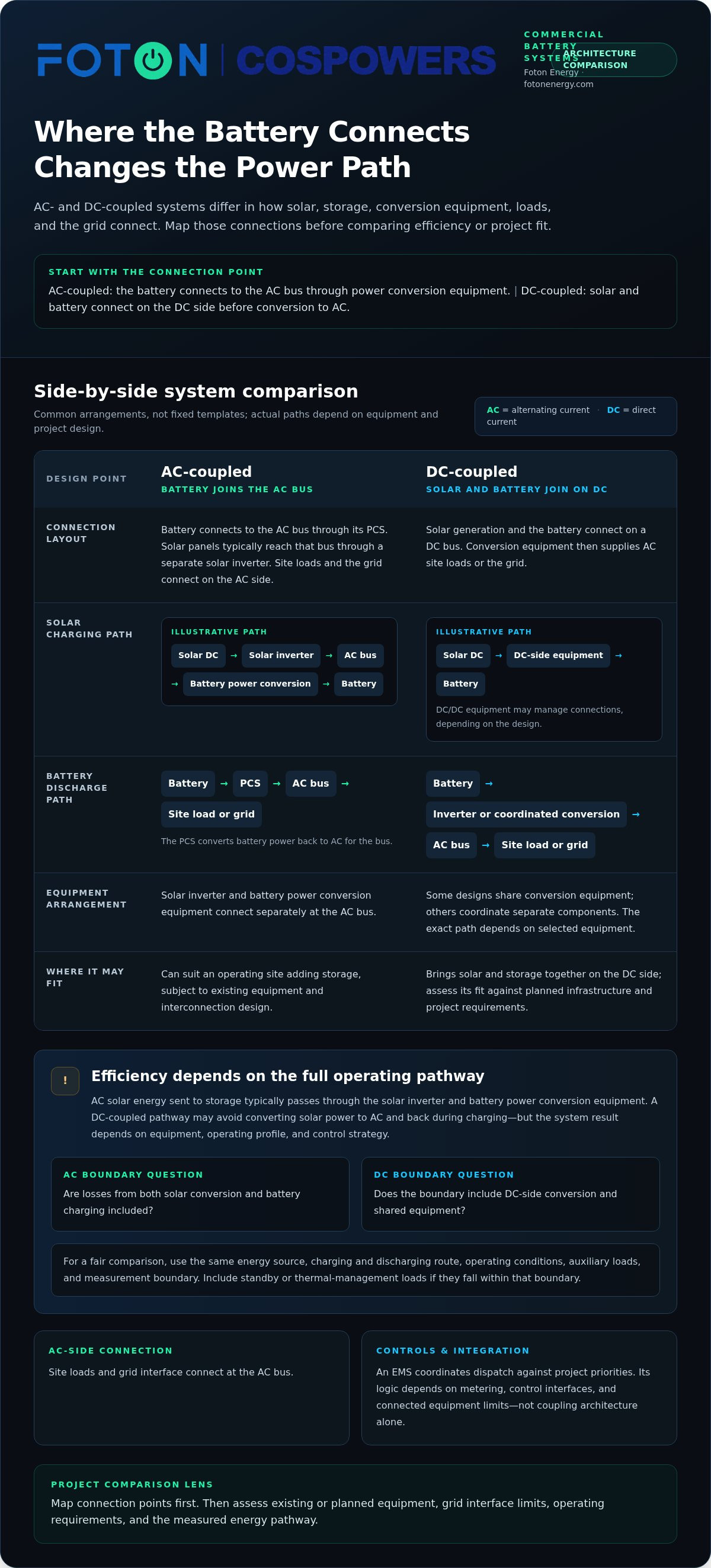
The defining difference is where the battery connects to the site’s electrical system. In an AC-coupled design, battery power conversion equipment connects storage to the alternating-current (AC) bus, where site loads and often solar inverters also connect. In a DC-coupled design, the battery and solar generation connect on the direct-current (DC) side before power is converted for AC loads or the grid. These are common arrangements, not fixed templates. Commercial BESS designs vary with equipment and project requirements.
An inverter converts DC electricity into AC electricity. A power conversion system (PCS) manages conversion between a battery and the AC system, including charging and discharging. The Battery Energy Storage System (BESS) includes more than the battery itself. Its connections to generation, loads, and the grid shape the system architecture.
How an AC-coupled commercial battery system is arranged
The battery connects through its PCS to an AC bus. Solar panels typically feed that bus through a separate solar inverter, while site loads and the grid connect on the AC side. This arrangement can suit an operating site adding storage: the existing solar inverter and battery conversion equipment connect at the AC bus, subject to the project’s equipment and interconnection design.
AC-coupled power path: Solar panels → solar inverter → AC bus ← battery ↔ PCS
Connected at the AC bus: Site loads and grid interface
During charging, the PCS converts AC power into a form the battery can store. During discharge, it converts battery power back to AC for the bus.
How a DC-coupled commercial battery system is arranged
In a DC-coupled design, solar generation and the battery connect on a DC bus before power reaches the AC system. Conversion equipment then supplies site loads or the grid. Depending on the design, DC/DC equipment may manage connections between the solar array, battery, and inverter. Some configurations share conversion equipment, while others coordinate separate components.
DC-coupled power path: Solar panels ↔ DC bus ↔ battery
Conversion path: DC bus → inverter or coordinated conversion equipment → AC bus
Connected at the AC bus: Site loads and grid interface
This layout brings solar and storage together on the DC side, but the exact power path depends on the selected equipment and system design. To compare AC-coupled vs DC-coupled commercial battery systems, first map these connection points, then assess how each topology fits the site’s existing or planned infrastructure.
How Coupling Architecture Affects Conversion, Controls, and Integration
The connection points determine which conversion stages energy passes through, but they do not predict how a complete system will perform. The U.S. Department of Energy’s Solar-Plus-Storage 101 also explains how solar and storage configurations shape integration.
Efficiency: compare the whole operating pathway, not one component
An efficiency comparison is meaningful only when both systems use the same energy source, charging and discharging route, operating conditions, auxiliary loads, and measurement boundary. An inverter’s conversion efficiency describes one component. Round-trip efficiency measures energy returned after charging across a defined system boundary.
The pathways below are simplified examples for solar charging and battery discharge. Actual equipment arrangements vary, and the comparison excludes auxiliary consumption unless it is included in the stated measurement boundary.
| Architecture | Illustrative charging path | Illustrative discharge path | Key boundary question |
|---|---|---|---|
| AC-coupled | Solar DC → solar inverter → AC bus → battery power conversion equipment → battery | Battery → power conversion equipment → AC bus → site load or grid | Are losses from both solar conversion and battery charging included? |
| DC-coupled | Solar DC → DC-side equipment → battery | Battery → inverter or coordinated conversion equipment → AC bus → site load or grid | Does the boundary include DC-side conversion and shared equipment? |
In an AC-coupled system, solar energy sent to storage typically passes through the solar inverter and the battery’s power conversion equipment. A DC-coupled pathway may avoid converting solar power to AC and back during charging, but the system result depends on the equipment, operating profile, and control strategy. Compare measured energy at consistent input and output points. Account for standby or thermal-management loads if they fall within the assessment boundary.
Controls and integration across solar, storage, and site loads
An energy management system (EMS) coordinates dispatch against project priorities, such as using stored solar energy, responding to site demand, or following grid signals. Its logic depends on metering points, available control interfaces, and the operating limits of connected equipment. These are design considerations, not automatic features of either coupling architecture.
Meter placement affects what the EMS can observe. Solar generation, battery charging and discharging, site consumption, and grid import or export may each require distinct measurements. Setpoints and dispatch logic must align with those readings and the grid interface so the system responds to a consistent view of power flows. For a deeper look at control strategies, read the AI-driven energy management systems guide.
Comparing AC-coupled vs DC-coupled commercial battery systems means assessing conversion routes alongside metering, EMS coordination, dispatch requirements, and grid-interface design. Learn about Foton Energy’s commercial BESS engineering support as you define the project’s integration requirements.
Which Commercial BESS Architecture Fits a Retrofit or New Project?
Project fit depends on the site’s electrical boundary, the equipment that will remain in service, and how storage must operate. For a retrofit, existing solar inverters, switchgear, metering, and grid connection help define the design brief. In a greenfield project, generation and storage can be planned together, but equipment selection still needs to match operating objectives and interconnection requirements.
For broader project context, see this commercial and industrial BESS strategic guide. The practical question is not which topology wins in general, but which one fits the site’s equipment boundary and performance priorities.
When an AC-coupled design may align with an existing site
An operating facility with solar generation and established AC infrastructure may consider an AC-coupled layout when adding storage. The battery’s conversion equipment connects on the AC side, while existing solar inverters can remain part of the generation path if the wider design supports that arrangement. This can make AC coupling relevant to a phased deployment, where the battery is added to an operating energy system.
That does not guarantee a simpler project. Engineering must examine switchgear capacity, protection and control interfaces, available interconnection capacity, metering, and coordination with existing generation and loads. If equipment needs replacement or modification, the project scope can change the comparison. Define the project boundary early to identify these dependencies.
When a DC-coupled design may align with a planned system
A greenfield solar-plus-storage project can assess generation and storage as a coordinated design. This includes whether a DC-side connection and shared or coordinated conversion equipment suit the intended power flows. It may be relevant when the project team is selecting the solar, battery, and conversion architecture together rather than integrating storage around equipment already in operation.
Plan for the full operating horizon, not just initial commissioning. Expansion plans, dispatch objectives, site-load needs, equipment limits, and the grid interface all influence whether the proposed configuration is suitable. Evaluate a shared conversion approach against those requirements and the actual equipment configuration. The topology alone does not establish compatibility.
Use these project conditions to structure an early comparison:
- Retrofit: Identify which inverters, switchgear, meters, and controls will remain in service.
- Co-located solar and storage: Define energy paths, dispatch objectives, and interfaces between generation and the battery.
- Greenfield: Coordinate equipment selection with interconnection limits, site operations, and future expansion.
For AC-coupled vs DC-coupled commercial battery systems, equipment replacement scope and project boundaries can matter as much as the nominal architecture. Map what exists, what will change, and how the BESS is expected to operate before comparing designs.
A Practical Framework for Comparing AC and DC Coupled Systems
Make the architecture decision from project evidence, not a generic efficiency ranking. Start with what the site needs to achieve, then test each AC-coupled vs DC-coupled commercial battery system against the same operating data and design boundaries.
Inputs to assemble before architecture selection
Gather the information that defines the project before comparing configurations:
- Set objectives: Define intended services, such as managing site demand, storing on-site generation, or providing backup. Identify the performance requirements for each.
- Build the site profile: Assemble interval load and generation data, operating schedules, and planned changes to site capacity or operations.
- Inventory equipment: Record existing inverters, switchgear, metering, protection, and control interfaces. Note what may remain in service or require change.
- Define the grid interface: Document the connection arrangement and relevant import, export, or interconnection limits that shape system operation.
- Compare feasible layouts: Assess each architecture against dispatch use cases, integration scope, lifecycle performance, maintainability, and future expansion.
This sequence connects demand patterns to system design. For example, a site with changing operating schedules should assess how each configuration would support its intended dispatch, rather than relying on a snapshot of peak demand.
How to assess design trade-offs transparently
Compare equivalent system boundaries, duty cycles, assumptions, and measurement methods. For efficiency, define the energy input and output points, then account consistently for relevant conversion stages and auxiliary loads. For lifecycle and operations, document maintenance access, equipment dependencies, planned expansion, and changes required to existing infrastructure.
Use a decision matrix to make trade-offs visible. It organizes the evidence without prescribing a universal winner.
| Consideration | Evidence to compare |
|---|---|
| Performance | Duty cycle, energy flows, dispatch objectives, and consistent measurement boundaries |
| Integration | Existing equipment, interface requirements, and replacement or modification scope |
| Operations | Maintainability, control coordination, and site operating requirements |
| Future needs | Expansion plans and changes in generation, load, or dispatch use |
Record assumptions, integration dependencies, technical risks, and unresolved decisions alongside the comparison. A project feasibility process makes uncertainty explicit and gives the design team a clear basis for the next stage. Read the BESS engineering consulting guidance for more on translating project requirements into a robust design. See Foton Energy’s commercial BESS engineering services.
From Architecture Choice to an Integrated Commercial BESS
Choosing an AC or DC connection is an early design decision, not a complete system specification. The architecture influences how battery hardware, power conversion, controls, thermal management, and safety measures work together. Treating these as connected design considerations helps keep project requirements aligned from initial engineering through integration and commissioning.
Align battery hardware, power conversion, and project controls
Battery chemistry alone does not determine whether an AC- or DC-coupled arrangement suits a project. Foton Energy (Foton Pty Ltd)'s LFP and sodium-ion storage systems can be evaluated within a project-specific architecture, alongside the selected conversion equipment, site interfaces, and operating objectives. The design needs to account for how the components fit together rather than treating the battery as a standalone choice.
Controls are part of that system-level view. An energy management system (EMS) must coordinate dispatch with generation, loads, and the grid interface according to the project’s intended operation. Thermal management and safety architecture also need to be considered as part of the integrated design. Coordinate their requirements and interfaces with the selected equipment and system layout, rather than leaving them as separate decisions after choosing the coupling architecture.
Plan the next engineering and procurement steps
Design progression starts with a clear project brief. Bring together site load and generation data, operating objectives, existing equipment and control interfaces, grid connection information, and plans for future changes. These inputs help frame engineering decisions, clarify equipment requirements, and identify integration dependencies before procurement and implementation planning advance.
Engineering, procurement, integration, and commissioning are linked workstreams. Engineering translates site requirements into a coordinated system design. Procurement follows the resulting equipment and interface needs. Integration connects system components and controls, while commissioning verifies operation against the project design and objectives. Decisions or changes in one workstream can affect the others, so clear technical coordination supports a consistent path from design to operation.
Foton Energy (Foton Pty Ltd) provides engineering consulting and commercial and industrial BESS, bringing advanced manufacturing heritage and energy storage solutions to diverse site profiles. This project-oriented combination brings battery hardware and engineering requirements into the same assessment, without assuming one coupling architecture will suit every site.
Use project objectives and site evidence to carry the AC-coupled vs DC-coupled commercial battery systems comparison into the next design stage. Discuss your commercial battery system requirements with Foton Energy (Foton Pty Ltd).
Turn the Architecture Decision into a Project-Ready Design
The right choice between AC-coupled vs DC-coupled commercial battery systems depends on the project boundary and operating priorities, not on a universal ranking. Compare conversion performance using consistent assumptions, then assess site load and generation, existing equipment, interconnection limits, dispatch needs, and expansion plans. These inputs connect architecture selection to controls, safety, thermal management, and integration requirements.
Foton Energy brings together commercial BESS, LFP and sodium-ion systems, AI-driven energy management, and engineering consulting. As Cospowers’ exclusive global strategic partner, Foton works with a Tier-1 energy storage manufacturer with more than 30 years of manufacturing heritage. This supports a project-oriented assessment of hardware and engineering needs as one coordinated design.
Move your project toward its next design stage with a clear view of its requirements. Discuss your commercial battery system requirements with Foton to take the next step toward a storage architecture aligned with your site and operational goals.
Frequently Asked Questions
What is the main difference between AC-coupled and DC-coupled commercial battery systems?
The main difference is where the battery connects relative to the system’s power conversion equipment. In an AC-coupled system, the battery connects to the AC bus through its power conversion system, alongside site loads and often solar inverters. In a DC-coupled system, the battery and solar generation connect on the DC side before power is converted for AC loads or the grid. Equipment configuration varies by project.
Is an AC-coupled or DC-coupled battery system more efficient?
Neither architecture is always more efficient across every commercial project. A DC-coupled pathway may involve fewer conversion stages when solar charges a battery, while actual performance depends on equipment, operating profile, controls, and auxiliary loads. AC-coupled performance depends on its conversion route and equipment. Compare complete system pathways using consistent measurement points and operating assumptions, rather than treating one component’s efficiency as the whole-system result.
Can a commercial battery be added to an existing solar system?
Yes, a commercial battery can be considered for an existing solar system, but the design depends on site equipment and operating requirements. An AC-coupled arrangement may connect battery power conversion equipment to the site’s AC bus alongside existing solar inverters. Engineering must assess the inverter and switchgear configuration, control and metering interfaces, interconnection limits, and any equipment changes needed. A site review establishes whether the proposed arrangement fits.
When is DC coupling worth considering for a commercial BESS?
DC coupling is worth evaluating when solar generation and storage can be designed together, particularly in a planned or greenfield project. The design team can assess whether a DC-side connection and shared or coordinated conversion equipment fit energy flows, dispatch objectives, and future expansion plans. Suitability still depends on the equipment configuration, site requirements, and grid interface. Including solar does not automatically make DC coupling the right choice.
How do I compare AC-coupled and DC-coupled battery efficiency?
Compare round-trip efficiency across equivalent system boundaries. Define the energy input and output points, charging source, discharge route, duty cycle, and operating conditions. Include the relevant conversion stages for each architecture, and account consistently for auxiliary consumption, such as thermal management, if it falls within the boundary. Keep component efficiency separate from system-level performance. Without aligned assumptions and measurement methods, headline figures may describe different operating pathways and cannot be compared directly.
Does battery chemistry determine whether a system should be AC-coupled or DC-coupled?
No. Battery chemistry and coupling architecture are related design considerations, but chemistry alone does not determine the system layout. The architecture also depends on power conversion equipment, solar configuration, site loads, controls, grid interface, and operating objectives. LFP and sodium-ion systems still need to be assessed within the project’s specific electrical design. Evaluate the complete system rather than treating battery chemistry as a shortcut to an AC or DC decision.
What information is needed to choose a commercial battery coupling architecture?
Start with project objectives and site data. Useful inputs include interval load and generation profiles, operating schedules, intended battery dispatch use cases, and plans for future capacity changes. Document existing inverters, switchgear, metering and control interfaces, plus grid connection and interconnection limits. These details help compare integration scope, operating performance, maintainability, and expansion needs. Engineering assessment can then test both architectures against consistent assumptions and the project’s actual requirements.


