

The right BESS control choice depends on the grid the system must support, not just the battery’s size. BESS for grid-forming applications can establish voltage and frequency, including when operating without the main grid. Grid-following BESS relies on an existing grid reference and cannot operate independently. This distinction affects where each option can work and what the project needs to deliver.
It is natural to focus first on power and storage capacity, but they answer different questions. Power describes how much the system can deliver at a time; capacity describes how much energy it can store. Both matter, alongside grid strength, operating mode and the response required during disturbances.
This comparison explains how grid-forming and grid-following controls differ, where grid-forming systems can operate, and how to assess power and capacity needs. It also covers control approaches, weak-grid and islanded operation, and the practical trade-offs that shape a project decision. The goal is to help match the system architecture to the network and the role it must perform.
Key Takeaways
- Choose inverter control based on the network conditions and whether the system must operate independently of the main grid.
- Assess weak-grid and islanding requirements alongside black-start capability when defining the system’s role.
- Use performance studies to examine how the system responds to disturbances, not just its normal operating conditions.
- Match power rating to the output required at a given moment and capacity to the energy the system must store and deliver over time.
- For commercial and industrial or utility-scale projects, align the storage architecture with the application and the grid services required.
Grid-forming and grid-following inverter control architectures
Control architecture determines whether a battery inverter follows an existing grid reference or establishes voltage and frequency itself. Before selecting a configuration, compare its control objective and operating reference with the strength of the network.
Grid-Forming Control
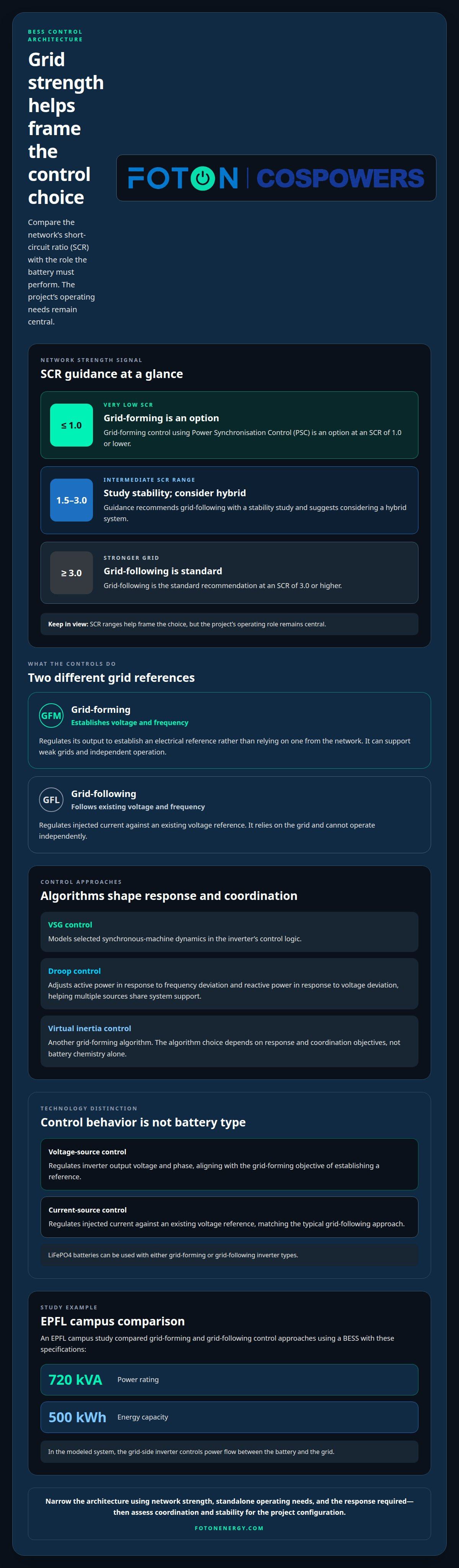
A grid-forming inverter regulates its output to establish voltage and frequency instead of relying on references from the network. BESS for grid-forming applications can therefore support systems that need an electrical reference, including during independent operation. Grid-forming control may use virtual synchronous machine behavior to emulate selected responses associated with synchronous machines. Grid-following control, by contrast, relies on an existing reference.
VSG and Droop Algorithms
Virtual synchronous generator (VSG) control models selected synchronous-machine dynamics in the inverter’s control logic. Droop control adjusts active power in response to frequency deviation and reactive power in response to voltage deviation, helping multiple sources share system support. Virtual inertia control is another grid-forming algorithm. The choice depends on response and coordination objectives, not battery chemistry alone.
Voltage- and Current-Source Control
Voltage-source control regulates an inverter’s output voltage and phase, aligning with the grid-forming objective of establishing a reference. Current-source control regulates injected current against an existing voltage reference, matching the typical grid-following approach. These terms describe control behavior, not different battery types: LiFePO4 batteries can be used with either grid-forming or grid-following inverter types.
Short-circuit ratio (SCR) offers one practical indicator of network strength. At an SCR of 1.0 or lower, grid-forming control using Power Synchronisation Control is an option. At an SCR of 3.0 or higher, grid-following is the standard recommendation. Between 1.5 and 3.0, guidance recommends grid-following with a stability study and suggests considering a hybrid system. These ranges help frame the choice, but the project’s operating role remains central.
| Control option | Grid reference | Typical operating role | Key distinction |
|---|---|---|---|
| Grid-forming | Establishes voltage and frequency | Weak grids or independent operation | Can provide the electrical reference |
| Grid-following | Follows existing voltage and frequency | Strong grids | Cannot operate alone |
An EPFL campus study compared both control approaches using a 720 kVA / 500 kWh BESS. In the modeled system, the grid-side inverter controls power flow between the battery and the grid. When specifying a BESS for grid-forming applications, use network strength, standalone operating needs, and required response to narrow the architecture. Then assess control coordination and stability for the project’s configuration.
Black start, islanding, and weak-grid operation
Grid-forming BESS can establish an electrical reference without the main grid, supporting black start and islanded operation. Key risks include unstable voltage or frequency, protection miscoordination, and demand exceeding available power or stored energy.
Black-Start Operation
Black start means using a grid-forming battery to energize a system without relying on the main grid’s voltage reference. A grid-following battery cannot perform this role alone because it needs an existing reference. The operating sequence must coordinate the inverter, available battery energy, connected loads and any generation that starts afterward.
For example, a site could use the BESS to establish voltage for essential loads before connecting additional equipment. Each added load changes the balance the inverter must maintain. A black-start plan should define which loads connect first and how the system responds if demand exceeds available output.
Island Operation and Protection
Island operation begins when a facility or network section runs separately from the main grid. The system must then balance local generation and demand while maintaining stable voltage and frequency. Protection settings must also account for the island’s operating state, since fault levels and power flows can differ from grid-connected conditions.
During a system split, coordination matters as much as inverter response. AEMO recommends that grid-forming BESS remain online during islanding and system-split events when AEMO and the network service provider agree, and stable voltage and frequency operation can be maintained. This makes operating limits, protection coordination and agreed control behavior central design considerations.
Weak-Grid Operation
Weak grids provide a less robust electrical reference, which can challenge control stability. A short-circuit ratio below 2.0 or 1.5 is identified as a weak-grid scenario where grid-forming BESS may be needed. The network’s fault strength, connected inverter controls, and expected operating conditions shape how the system should respond.
For a weak-grid study, model the BESS alongside other connected sources and representative loads. Test voltage and frequency response as output or network configuration changes, then assess whether the control settings maintain stable operation. This helps distinguish a system designed for routine grid support from one expected to sustain an island.
Across black start, islanding, and weak-grid operation, assess three linked limits: inverter power, stored energy, and protection coordination. A residential project considering backup operation can also explore Residential Storage Systems as a related storage application.
Grid-forming performance studies and project examples
Grid-forming BESS projects are assessed by modeling disturbances, evaluating control response and validating the connected system against its performance requirements. During commissioning, the project team checks that the installed controls behave consistently with the modeled response and agreed operating settings.
A modeled example tests a sudden 50% reduction in PV output at 1.5 seconds. In that scenario, the grid-forming BESS provides inertial power, primary response, and reactive power to help maintain stable operation. This type of contingency study reveals how the battery and inverter respond when connected generation changes sharply.
Build a Contingency Study
Start with the network configuration, connected generation, BESS controls, and operating conditions that matter to the project. Then simulate a defined disturbance, such as the PV reduction at 1.5 seconds, and observe voltage, frequency, active power, and reactive power response. Comparing these signals helps show whether the controls support the intended system behavior.
Response speed is one useful measure, but it isn’t the only one. Grid-forming and grid-following BESS can differ in how quickly they respond, so response speed should be assessed alongside stability. A study should interpret response alongside stability: a fast change is not useful if it causes poorly controlled voltage or frequency behavior.
Tune for Stability and Response
Control tuning balances the behavior required under different network conditions. AEMO recommends prioritising stability of response at low fault levels over response speed at high fault levels when those objectives conflict. This trade-off matters because settings optimized for one condition may not provide the best behavior across every contingency.
Use project studies to compare candidate settings against the disturbance cases and operating modes the system must support. Record the selected response targets, modeled assumptions and observed results together. This creates a traceable basis for commissioning and later assessment if the network or operating requirements change.
Assess IEEE 2800 Performance
IEEE Standard 2800-2022 sets out interconnection requirements for inverter-based resources. A project example evaluates the PV plant, BESS unit, and controllers against IEEE 2800, treating the plant as a connected system rather than assessing the battery inverter alone.
For commissioning, carry the study’s defined cases into checks of the installed controls and their response. Compare observed behavior with the model and applicable project performance requirements, then document deviations and corrective settings. This connects simulation results to the operating installation without assuming that one test procedure suits every network.
Renewable penetration and inverter-based resources
Renewable-heavy grids need BESS that can support voltage, frequency and power balance as inverter-based generation changes. Grid-forming systems can provide inertial power, primary response and reactive power, helping maintain stable operation as renewable output varies.
Renewable-Heavy Grid Needs
Inverter-based resource (IBR) penetration helps indicate how much a grid relies on resources connected through power electronics. The guide recommends grid-forming BESS where IBR penetration exceeds 70%, grid-following BESS below 50%, and a hybrid approach between 50% and 70%.
These thresholds frame a planning decision, not a substitute for examining network strength and operating conditions. At higher penetration, a grid-forming BESS can establish a voltage and frequency reference while supporting changing renewable output. Below 50%, grid-following control may suit a stronger grid that already provides a reference.
Inverter Functions and Capabilities
A grid-forming inverter controls voltage and frequency rather than simply following an external reference. In renewable-heavy networks, this function can support active-power balance, reactive-power needs and responses to disturbances. These capabilities matter because wind and solar output can change while grid conditions also vary.
Assess the required services against the system’s operating role. For example, if a project needs to support a grid zone with IBR penetration above 70%, evaluate whether the inverter can provide the intended voltage and frequency support alongside its power response. The required capability depends on the network’s needs, not penetration alone.
Inverter and Battery Technologies
Grid-forming and grid-following describe inverter control, not battery chemistry. LiFePO4 batteries can be paired with either inverter type, so selecting a battery technology does not by itself determine whether the system can form the grid.
Specify the inverter controls and battery as parts of one energy storage system. The inverter governs how stored energy interacts with voltage, frequency and grid conditions; the battery supplies the energy available for that response. A design review should align the control mode, required grid services and operating profile.
Use the penetration bands as an initial screen, then compare the grid’s strength and the services required. For 50% to 70% IBR penetration, the hybrid option combines grid-forming and grid-following approaches, while the project’s network conditions guide the final configuration.
The page identifies grid-forming BESS for weak grids and grid-following BESS for strong grids, making grid strength a key selection consideration.
Battery energy storage system capacity and power rating
Power and energy describe different limits in a battery energy storage system. Power, measured in MW, is the output available at a given moment; energy capacity, measured in MWh or MWhr, is the stored energy available over time. BESS for grid-forming applications needs both ratings aligned with the service it must provide.
A modeled grid-scale BESS has a storage capacity of 60 MWhr and maximum power of 35 MW. Dividing capacity by maximum power gives about 1.7 hours of output at that power, before accounting for operating limits. This ratio helps interpret a system’s energy duration, but it doesn’t establish whether the system can meet a project’s full operating requirements.
Start sizing by defining the task. A short, high-power response emphasizes inverter output; sustained support places greater emphasis on stored energy. If the system must provide both, specify the required power profile and duration together. For BESS for grid-forming applications, a high MW rating can obscure insufficient energy for a longer event, while large capacity may not provide the required instantaneous output.
- Define the service: Identify the power response and duration required for the operating case.
- Set the power rating: Match inverter output to the maximum demand or support level.
- Set the energy capacity: Match stored energy to how long the system must sustain that output.
- Review the operating profile: Assess how changing loads, renewable output, and grid conditions affect dispatch.
For grid-forming operation, assess power and energy against the same system event. A disturbance may call for rapid active and reactive power response, while the operating plan may also require continued support afterward. The inverter’s response capability and the battery’s energy supply must work together, rather than being treated as separate sizing decisions.
Use the 60 MWhr and 35 MW example as a calculation, not a universal specification. Actual requirements depend on the response profile, support duration, connected loads, and the energy available under the project’s operating limits. A clear specification states the required power, energy, and operating scenario, so technical studies can assess whether the system meets its intended role.
Align your project’s power and capacity requirements before finalizing the system design. Plan your storage power and capacity around the services the system must deliver.
Foton Energy (Foton Pty Ltd): C&I BESS
Foton Energy (Foton Pty Ltd) offers C&I BESS for commercial and industrial projects evaluating storage against grid-forming requirements. Consider this offering when you need to align the system’s operating role, inverter control approach, power rating and energy capacity. Defining these needs together connects the technical comparison to a practical system decision.
Foton Energy also offers Utility-Scale Storage for larger-scale storage applications, as well as Residential Storage Systems and Data Centre & Telco Backup for those distinct use cases. Choose the application according to the project’s purpose and operating requirements.
For a discussion about C&I BESS and your project requirements, contact Foton Energy (Foton Pty Ltd).
Turn the Design Decision Into a Project Path
Treat BESS for grid-forming applications as part of the network’s operating architecture, not as an isolated equipment choice. The next step is to translate the project’s intended role into a clear design basis: expected operating modes, system interfaces, control objectives and the evidence needed to validate performance.
A clear design basis can align technical teams around a shared project scope before procurement and integration decisions are finalized. It also gives the project a practical reference point as network conditions and operational priorities evolve. Foton Energy (Foton Pty Ltd) supports storage projects through its C&I BESS, Residential Storage Systems and Utility-Scale Storage offerings.
Bring your project requirements into the next planning discussion and identify the storage pathway that fits. Contact Foton Energy (Foton Pty Ltd) to discuss the next step for your project. A well-defined starting point can help turn a control choice into a coordinated, resilient system.
Frequently Asked Questions
What is a grid-forming BESS and how does it differ from a grid-following battery?
A grid-forming BESS uses inverter controls that establish an electrical reference; a grid-following battery synchronizes with a reference already present. This distinction concerns the inverter’s control mode, not the battery chemistry. For project planning, identify whether the system must help operate an electrical island or will always connect to a grid that provides the reference. That requirement helps narrow the control approach.
How does grid-forming control provide voltage and frequency support?
Grid-forming controls regulate inverter output to support voltage and frequency at the connection point. Active-power response helps address frequency changes, while reactive-power response supports voltage. The actual response depends on control settings and the connected network. For example, a project study can examine how those outputs behave when generation changes, then assess whether the system’s response suits its intended role.
What are typical power, energy, and response-time requirements for grid-forming BESS?
There is no single rating that fits every project. Power requirements depend on the maximum output needed at a moment; energy capacity depends on how long the system must sustain its role. Response requirements should describe the event, measured output and time profile the system must meet. Define these together, since a high power rating alone does not show how long the battery can provide support.
How much does a grid-forming BESS cost compared with a grid-following BESS?
Grid-forming BESS generally has higher upfront cost than grid-following BESS, but the difference depends on the project configuration. Relevant factors include inverter capabilities, power and energy requirements, integration scope and site conditions. Project pricing depends on the case and is provided after a quote request. A useful comparison weighs the required grid services and operating needs against the system’s upfront cost.
What technical standards and grid-connection rules apply to grid-forming BESS in the United States?
Applicable requirements can include IEEE 1547 and UL 9540, while IEEE Standard 2800-2022 covers interconnection requirements for inverter-based resources. The relevant utility may also require project approval. These standards and approval processes serve different purposes, so identify the interconnection requirements for the project and the standards that apply to its equipment and system design. Requirements can depend on the utility and project configuration.
What are examples of operating grid-forming BESS projects and their performance?
Australia’s Western Downs Battery has had a grid-forming upgrade at a scale of 540 MW. It is a project-scale example, but capacity alone doesn’t show how a system performs under a specific grid event. To assess performance, examine evidence for the operating conditions that matter to your project, including the disturbance tested, measured response, and behavior of connected equipment.


